The internet's cheapest motorized, belt driven, 48" DIY camera rail
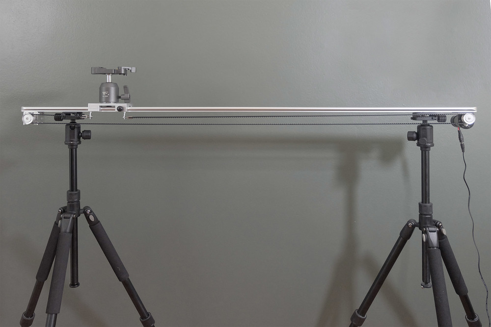
A camera slider is an indispensable tool for producing 3D lenticular prints and smooth video panning shots. Here we look at making a large motorized slider for a variety of applications. This DIY build is focused on creating a solid, reliable tool on the cheap, just over $250, using as few part sources as possible. Our slider:
- Big
- Motorized
- Belt driven
- Battery operated
- Light weight
- Easy to source
- Easy to assemble
- Inexpensive
The system uses a variable speed controller that operates forward and backward and a generous lithium battery pack for many hours of use in the field. Its built around the Opteka GLD-400 47-inch Camera Track Slider and includes a complete parts list with links. It is a DIY project requiring a few modifications, but the tools and skills are basic.
Tools
Drill, 5/32" drill bit, soldering iron, metal file, phillips screw driver, 3/32” hex key, 1/16” hex key.
Parts
Parts list, with prices, is here
MODIFICATIONS
Step 1
Enlarge the two holes indicated on the aluminum channel using a 5/32" drill bit.
Step 2
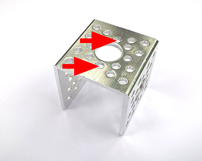
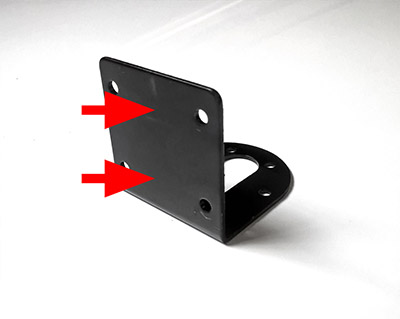
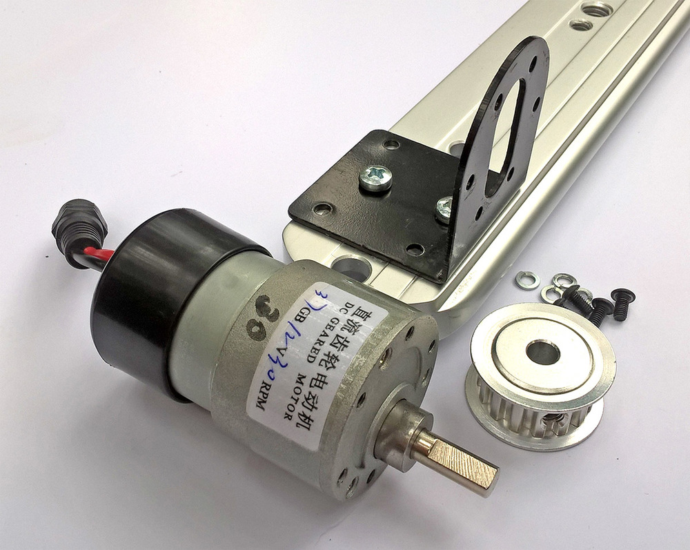
Drill two 5/32" holes on the motor mount using this template.
Step 3
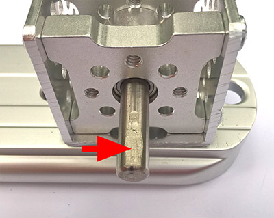
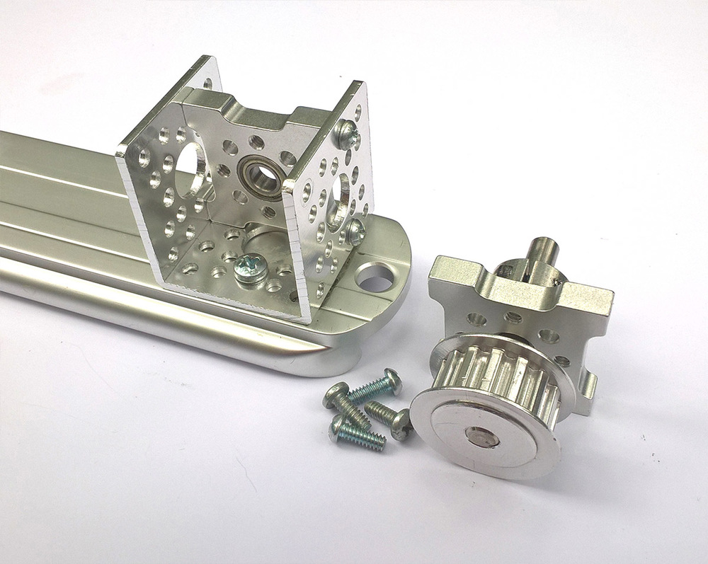
File a flat area on the 1/4" shaft. This is needed to keep the pinion pulley from slipping. In the picture this is shown attached to the pillow block bearing but is best clamped and filed prior to assembly.
Step 4
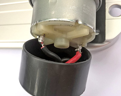
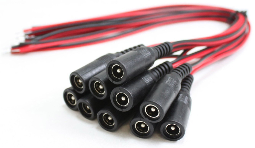
Solder a female pigtail wire to motor leads. If using the plastic cap, drill hole for wire and place through before attaching to motor.
Step5
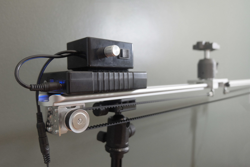
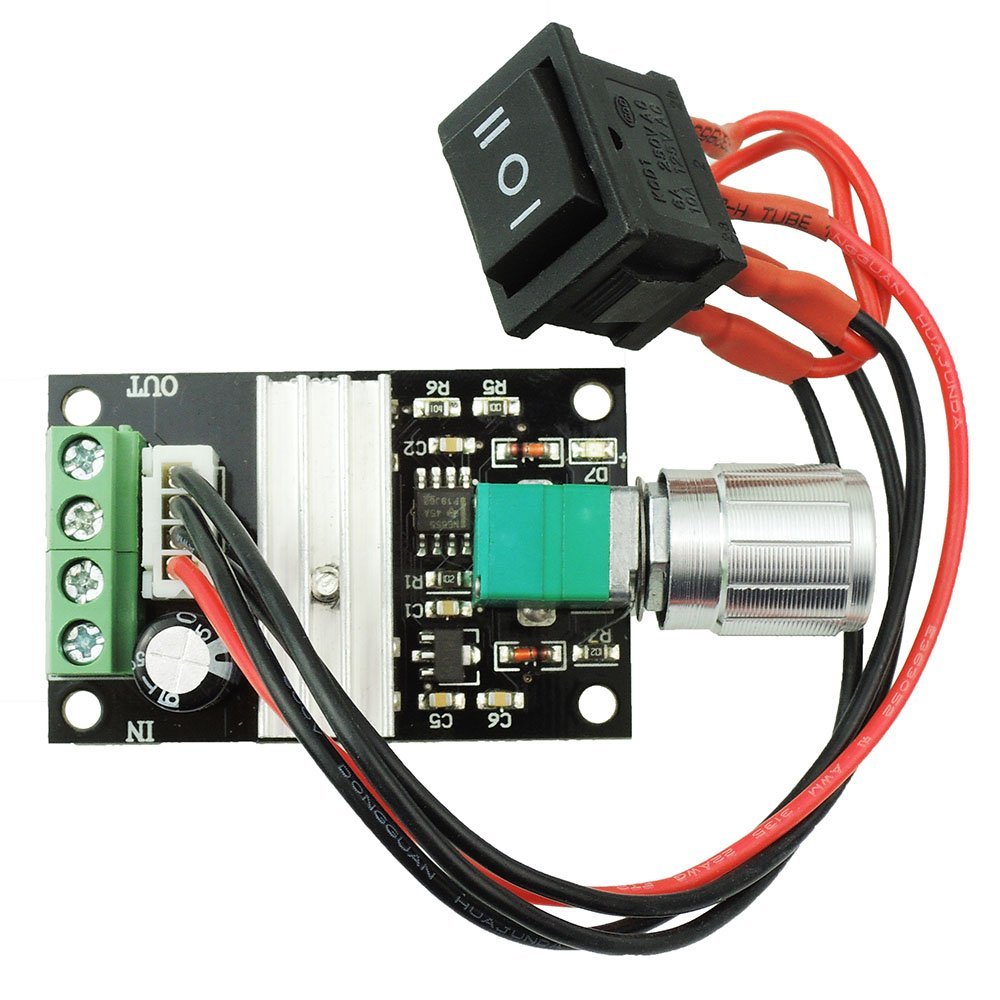
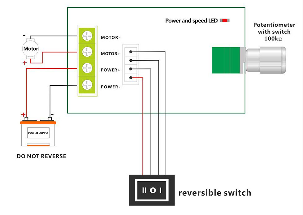
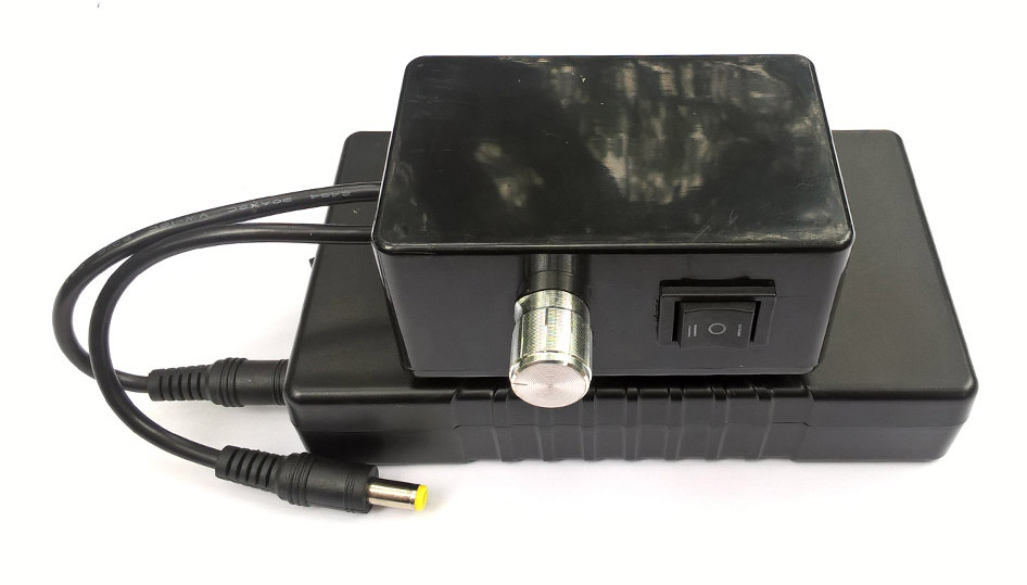
Cut the outbound wire that comes with the battery into two equal lengths. Strip 1/4" insulation from the ends of the wires and attach to controller. Wires from the battery go to the IN side, wires to the motor go to the OUT side.
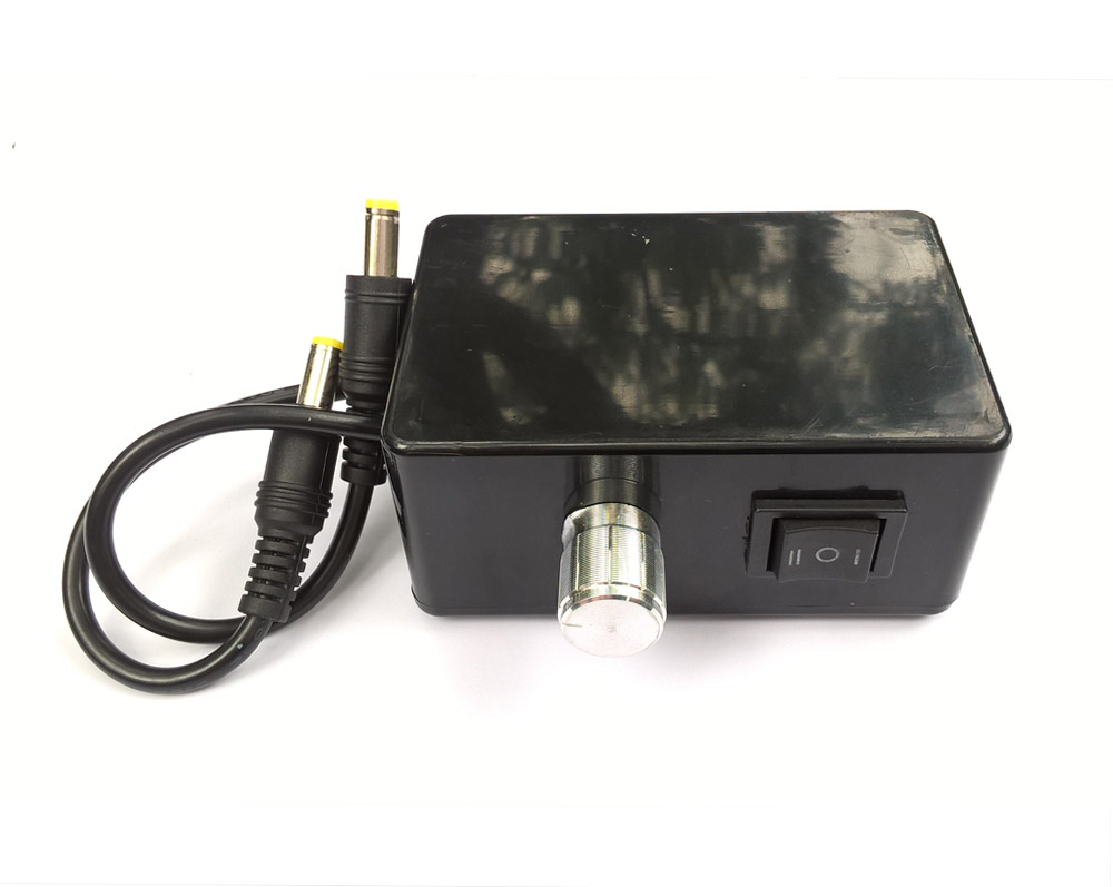
Our placement of the controller in the black box was uncomfortably tight, it is probably easiest if the knob comes out of the narrow end of the box. The box is primarily an aesthetic housing for the controller so build to suit your design needs. Note: Cutting a square hole for the rocker switch can be done by drilling small holes along the edges of your proposed opening and then flattening/smoothing with a file.
ASSEMBLY
Step 1
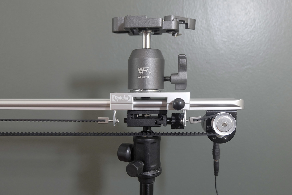
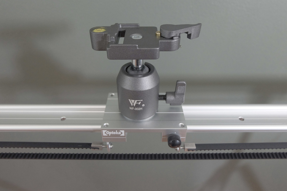
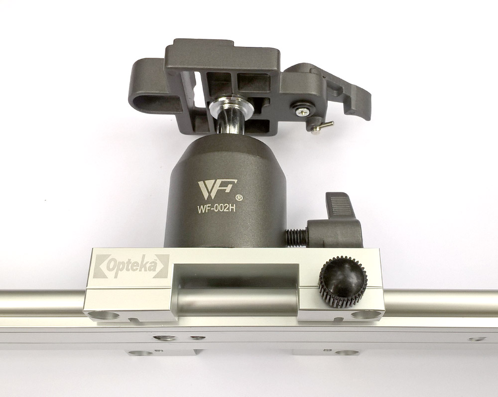
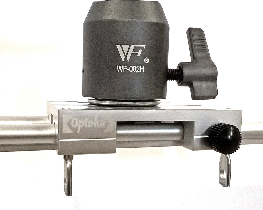
Screw the ball head camera mount to the platform. Place the sliding platform onto the glide rails and lock to keep from moving.
Step 2
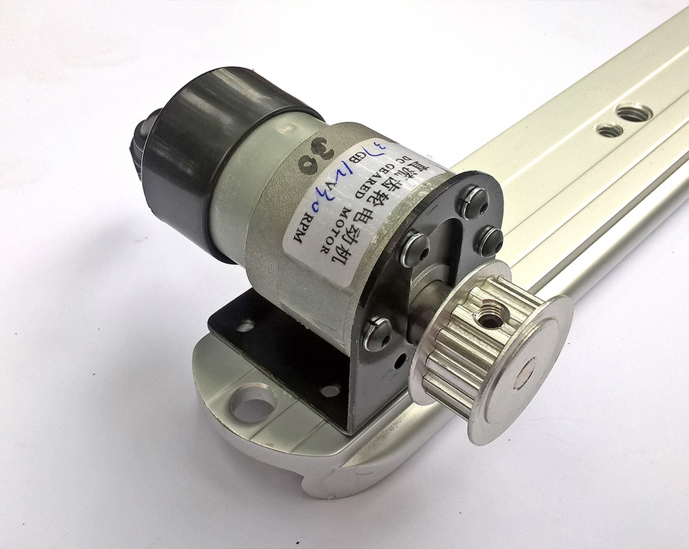
Attach the motor mount to the rail using the screws supplied for the rail feet. Attach the motor to the mount using 4 3m screws and lock washers. Slide the 6mm pinion pulley onto the motor shaft and tighten with the 3/32” hex key.
Step 3
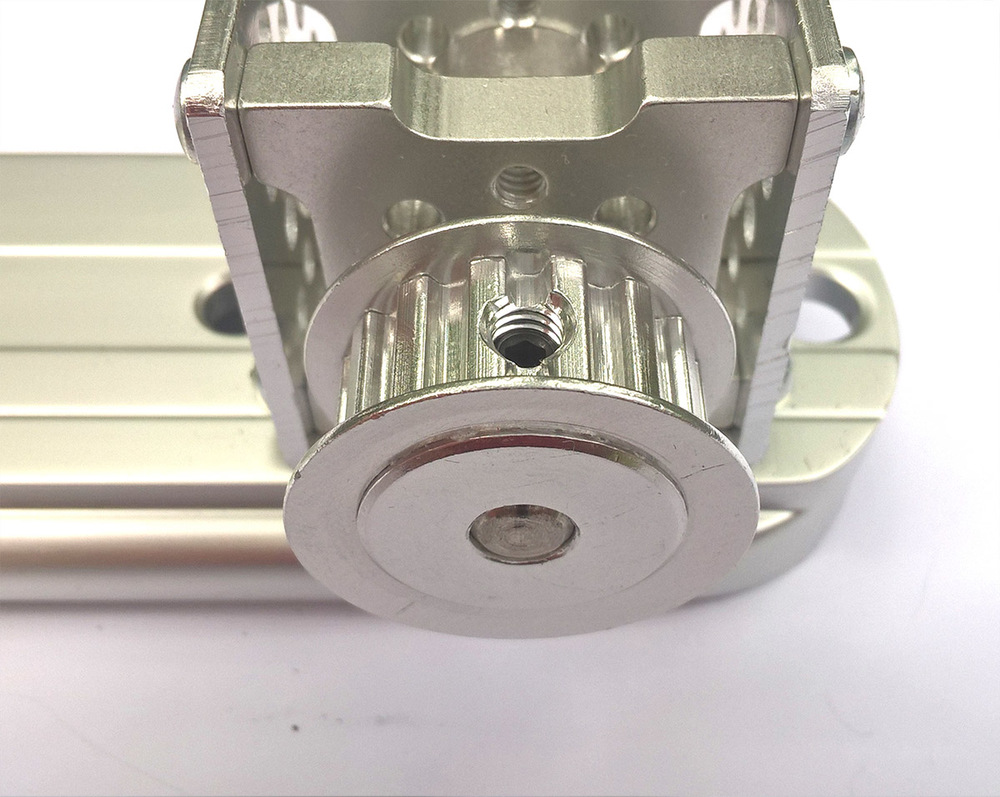
Attach the aluminum channel to the rail using the screws supplied for the rail feet. Assemble the pillow block bearings, 1/4" shaft, 1/4" pinion pulley and clamping collar as shown. The clamping collar prevents the shaft from sliding out of the bearings. The collar and pulley both use the 3/32” hex key.
Step 4
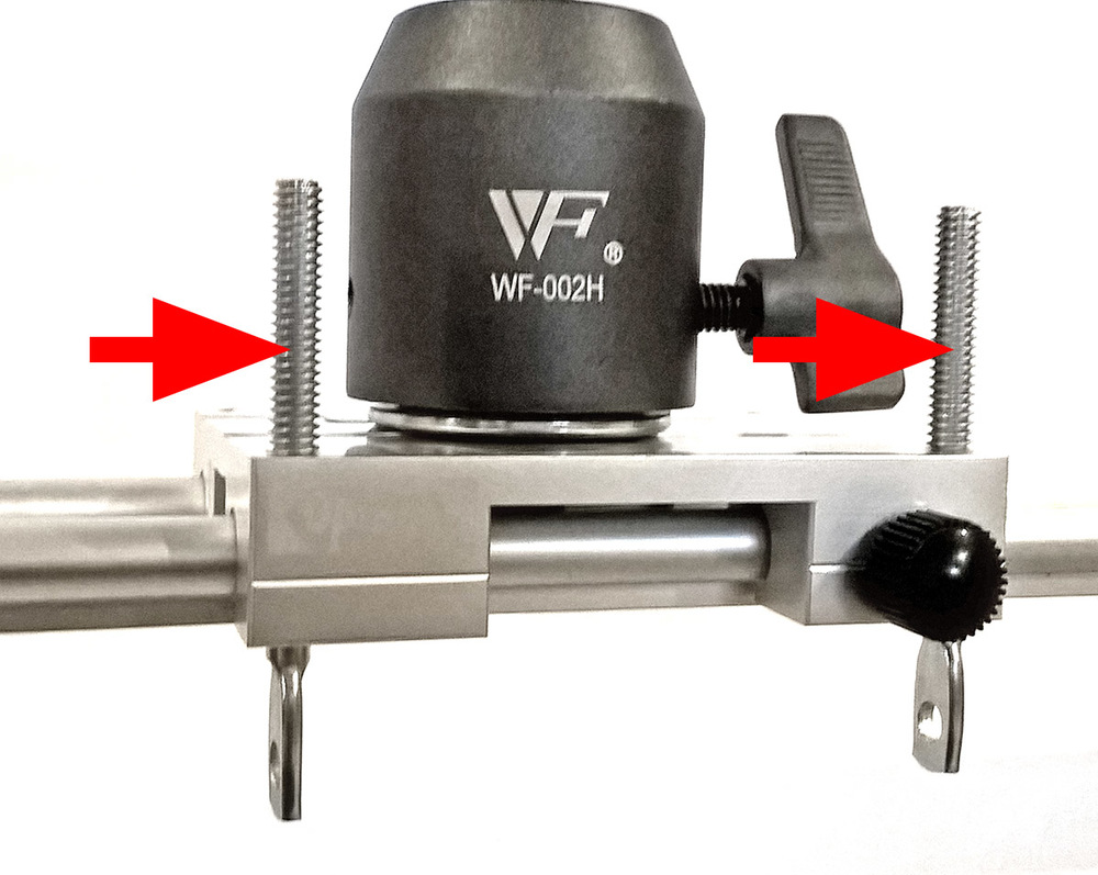
Screw push rods into platform's threaded holes. Since these rods are available only in 3" lengths it may be desirable to cut them to size with a hacksaw.
Step 5
Attach belt. The moment of inspired design with this project is the push rod / belt fastener system, a simple and effective method for attaching and tensioning the belt. Determine the length of belt necessary and cut. Fasten the XL belt mount to the ends of the belt using the 1/16” hex key, place belt into position and tension the belt using 2 - 6/32 screws.
Step 6
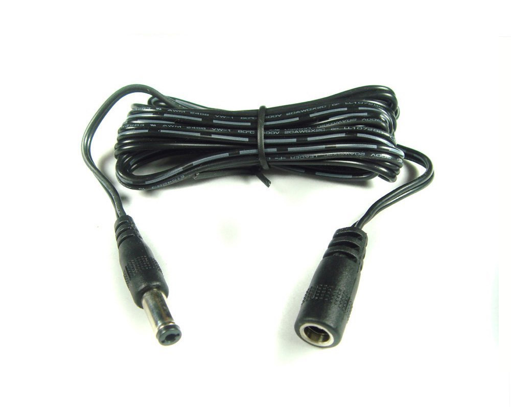
Attach 6 foot extension cable to motor and controller. Congratulations, you are done!
Remarks
This simple slider works amazingly well. It can be slowed to an almost imperceptible crawl or sped up to the full 30 RPM speed, allowing a range of utility. It works horizontally or on an incline, and can lift 5 pounds vertically without stalling. It is extremely light weight and portable and the battery lasts a long time between charges.
Considerations
- The slider should be stopped before the belt fastener reaches the pinion pulleys on either end. Its unclear what effect repeated stalling at the ends of the rail will have on the motor and should be avoided.
- Beware the brake on the sliding platform! If the motor is struggling or lurching be sure the platform is not locked.
- The motor is quiet but not silent. At slow speeds motor noise may not be audible but panning video at full speed will record some amount of noise.
- For faster pans or more rapid lenticular shots a 60 RPM motor is also available that fits the mount.
- Two tripods with narrow heads are recommended. A single tripod cannot sufficiently carry the weight of a camera without effecting the shot. Amazon has a sturdy, light-weight tripod here.
- For help in creating optimal lenticular sequences using a camera slider see our tutorial on Photographing for Lenticular Printing.
